EFFECT OF SPECIMEN GEOMETRY
The toughness, or resistance to crack growth, of a material is governed by the energy absorbed as the crack moves forward. In an extremely brittle material such as window glass, this energy is primarily just that of rupturing the chemical bonds along the crack plane. But as already mentioned, in tougher materials bond rupture plays a relatively small role in resisting crack growth, with by far the largest part of the fracture energy being associated with plastic flow near the crack tip.
A “plastic zone” is present near the crack tip within which the stresses as predicted would be above the material’s yield stress 'σY' . Since the stress cannot rise above 'σY' , the stress in this zone is 'σY' rather than that given. To a first approximation, the distance rp this zone extends along the x-axis can be found with (θ = 0) to find the distance at which the crack tip stress reduces to 'σY'
[ σy = σY = Ki/√2πrp ]
[ rp = K^2 i/2πσ^2/Y ]
This relation is illustrated. As the stress intensity in increased either by raising the imposed stress or by crack lengthening, the plastic zone size will increase as well. But the extent of plastic flow is ultimately limited by the material’s molecular or microstructural mobility, and the zone can become only so large. When the zone can grow no larger, the crack can no longer be
constrained and unstable propagation ensues. The value of Ki at which this occurs can then be considered a materials property, named Kic.
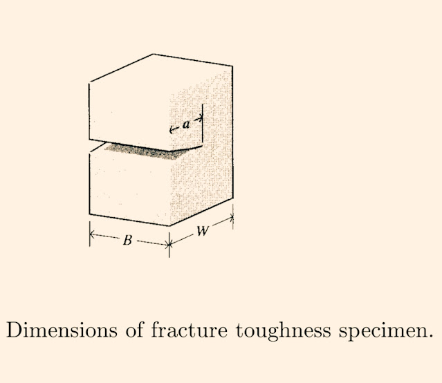
In order for the measured value of Kic to be valid, the plastic zone size should not be so large as to interact with the specimen’s free boundaries or to destroy the basic nature of the singular stress distribution. The ASTM specification for fracture toughness testing 9 specifies the specimen geometry to insure that the specimen is large compared to the crack length and the plastic zone
[ a, B,(W − a) ≥ 2.5 (Ki/σY)^2 ]
A great deal of attention has been paid to the important case in which enough ductility exists to make it impossible to satisfy the above criteria. In these cases the stress intensity view must be abandoned and alternative techniques such as the J-integral or the crack tip opening displacement method used instead. The reader is referred to the references listed at the end of the chapter for discussion of these approaches.
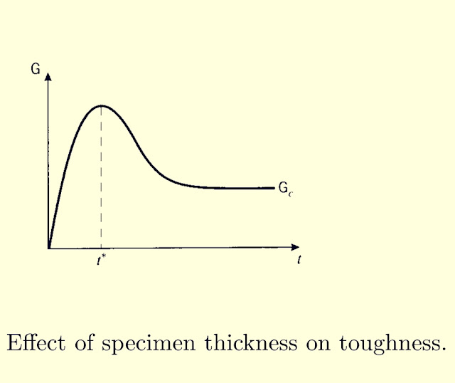
The fracture toughness as measured by Kc or Gc is essentially a measure of the extent of plastic deformation associated with crack extension. The quantity of plastic flow would be expected to scale linearly with the specimen thickness, since reducing the thickness by half would naturally cut the volume of plastically deformed material approximately in half as well. The toughness therefore rises linearly, at least initially, with the specimen thickness. Eventually, however, the toughness is observed to go through a maximum and fall thereafter to a lower value. This loss of toughness beyond a certain critical thickness t* is extremely important in design against fracture, since using too thin a specimen in measuring toughness will yield an unrealistically optimistic value for GC. The specimen size requirements for valid fracture toughness testing are such that the most conservative value is measured.
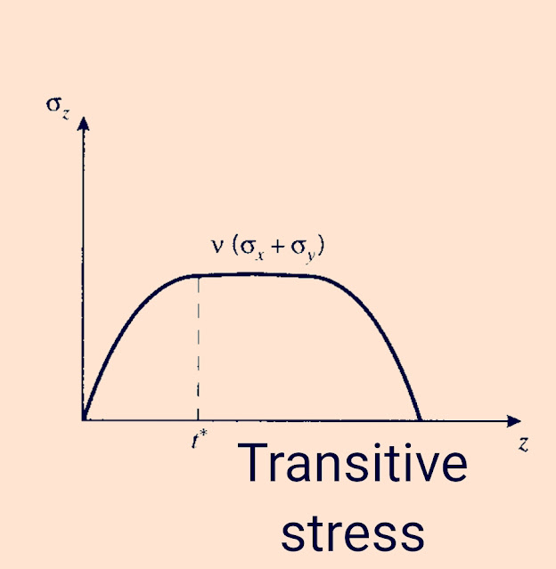
The critical thickness is that which causes the specimen to be dominated by a state of plane strain, as opposed to plane stress. The stress in the through-thickness 'z' direction must become zero at the sides of the specimen since no traction is applied there, and in a thin specimen the stress will not have room to rise to appreciable values within the material. The strain in the 'z' direction is not zero, of course, and the specimen will experience a Poisson contraction given by "€z = ν(σx + σy)". But when the specimen is thicker, material near the center will be unable to contract laterally due to the constraint of adjacent material. Now the 'z-direction' strain is zero, so a tensile stress will arise as the material tries to contract but is prevented from doing so. The value of σz rises from zero at the outer surface and approaches a maximum value given by" σz ≈ ν(σx + σy)" in a distance t*. To guarantee that plane strain conditions dominate, the specimen thickness t must be such that
( t >> 2t* )
The triaxial stress state set up near the center of a thick specimen near the crack tip reduces the maximum shear stress available to drive plastic flow, since the maximum shear stress is equal to one half the difference of the largest and smallest principal stress, and the smallest is now greater than zero. Or equivalently, we can state that the mobility of the material is constrained by the inability to contract laterally. From either a stress or a strain viewpoint, the extent of available plasticity is reduced by making the specimen thick.
@fizaengineer ......Sk najmul ( munna )
Follow me:-
https://m.facebook.com/fizaengineer/
https://m.webtalk.com/sknajmulhaque/
https://m.dailymotion.com/fizaengineer/
Please Read this ....


0 comments:
Post a Comment
Please do not enter any spam link in the comment box.