YIELD & PLASTIC FLOW, WITH MULTIAXIAL STRESS STATE.
YIELD AND PLASTIC FLOW
In the overview of the tensile stress-strain curve in Chapter 1, we described yield as a permanent molecular rearrangement that begins at a sufficiently high stress, denoted 'σY '. The yielding process is very material-dependent, being related directly to molecular mobility. It is often possible to control the yielding process by optimizing the materials processing in a way that influences mobility. General purpose polystyrene, for instance, is a weak and brittle plastic often credited with giving plastics a reputation for shoddiness that plagued the industry for years. This occurs because polystyrene at room temperature has so little molecular mobility that it experiences brittle fracture at stresses less than those needed to induce yield with its associated ductile flow.But when that same material is blended with rubber particles of suitable size and composition, it becomes so tough that it is used for batting helmets and ultra-durable children’s toys. This magic is done by control of the yielding process. Yield control to balance strength against toughness is one of the most important aspects of materials engineering for structural applications, and all engineers should be aware of the possibilities.
* Yield stress 'σY' as determined by the 0.2% offset method.
Another important reason for the understanding yield is more prosaic, if the material is not allowed to yield, it is not likely to fail. This is not true of brittle materials such as ceramics that fracture before they yield, but in most of the tougher structural materials no damage occurs before yield. It is common design practice to size the structure so as to keep the stresses in the elastic range, short of yield by a suitable safety factor. We therefore need to be able to predict when yielding will occur in general multidimensional stress states, given an experimental value of 'σY' .
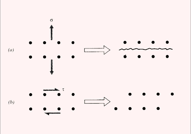
Fracture is driven by normal stresses, acting to separate one atomic plane from another. Yield, conversely, is driven by shearing stresses, sliding one plane along another. These two distinct mechanisms are illustrated. Of course, bonds must be broken during the sliding associated with yield, but unlike in fracture are allowed to reform in new positions. This process can generate substantial change in the material, even leading eventually to fracture (as in bending a metal rod back and forth repeatedly to break it). The “plastic” deformation that underlies yielding is essentially a viscous flow process, and follows kinetic laws quite similar to liquids. Like flow in liquids, plastic flow usually takes place without change in volume, corresponding to Poisson’s ratio
[ ν = 1/2 ]
(a).Cracking is caused by normal stresses.
(b). sliding is caused by shear stresses.
MULTIAXIAL STRESS STATES
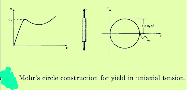
The yeld stress 'σy' is usually determined in a tensile test, where a single uniaxial stress acts. However, the engineer must be able to predict when yield will occur in more complicated real-life situations involving multiaxial stresses. This is done by use of a yield criterion, an observation derived from experimental evidence as to just what it is about the stress state that causes yield. One of the simplest of these criteria, known as the maximum shear stress or Tresca criterion, states that yield occurs when the maximum shear stress reaches a critical value τmax = k. The numerical value of k for a given material could be determined directly in a pure-shear test, such as torsion of a circular shaft, but it can also be found indirectly from the tension test as well. Mohr’s circle that the maximum shear stress acts on a plane 45◦ away from the tensile axis, and is half the tensile stress in magnitude,
[ then k = σY /2 ]
Mohr’s circle construction for yield in uniaxial tension.
In cases of plane stress, Mohr’s circle gives the maximum shear stress in that plane as half the difference of the principal stresses,
[ τmax = σp1 − σp2/ 2 ]


0 comments:
Post a Comment
Please do not enter any spam link in the comment box.